Boards
Each cat's main board and the module boards wired to it. Pick a module to see which of its pins goes to which pin of the main board.
Left cat
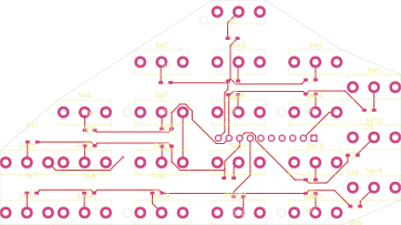
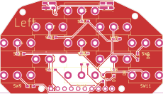
Left finger module, 21 keys → main board
Left finger module, 21 keys left-F21 in review
Its header J1 (PH2.54-1X10P-H25 (LCSC C42431810), 1×10 vertical 2.54 mm, bottom side) stands out of the board's bottom; the drawing
shows the bottom face, ▪ marks pin 1. The board's page
- The cable is not measured yet: its kind, length and where each end is soldered are unknown.
The main board's pins are measured off Banana Pi's dimension drawing (bpi_leaf_s3_board_board_dimension.jpg), which dimensions none of them; not yet measured on a board, ±0.1 mm.
- key matrix
| Header pin | Signal | Main-board pin | Row · position | What it carries |
|---|---|---|---|---|
| J1·1 | FO1 | GPIO1 pin 26 | J3·4 | matrix column 1 (firmware column 0), output — driven low to scan; index · outer |
| J1·2 | FO2 | GPIO2 pin 27 | J3·5 | matrix column 2 (firmware column 1), output — index · inner |
| J1·3 | FO3 | GPIO42 pin 28 | J3·6 | matrix column 3 (firmware column 2), output — middle; the left board's m0 is on column 1 |
| J1·4 | FO4 | GPIO41 pin 29 | J3·7 | matrix column 4 (firmware column 3), output — ring |
| J1·5 | FO5 | GPIO40 pin 30 | J3·8 | matrix column 5 (firmware column 4), output — pinky · inner |
| J1·6 | FO6 | GPIO39 pin 31 | J3·9 | matrix column 6 (firmware column 5), output — pinky · outer |
| J1·7 | FI1 | GPIO38 pin 32 | J3·10 | matrix row 1 (firmware row 0), input, pull-up — physical bottom row |
| J1·8 | FI2 | GPIO37 pin 33 | J3·11 | matrix row 2 (firmware row 1), input, pull-up |
| J1·9 | FI3 | GPIO36 pin 34 | J3·12 | matrix row 3 (firmware row 2), input, pull-up |
| J1·10 | FI4 | GPIO35 pin 35 | J3·13 | matrix row 4 (firmware row 3), input, pull-up — physical top row |
Left thumb module, 11 keys → main board
Left thumb module, 11 keys left-T11 qualified
Its header J1 (PH2.54-1X10P-H25 (LCSC C42431810), 1×10 vertical 2.54 mm, bottom side) stands out of the board's bottom; the drawing
shows the bottom face, ▪ marks pin 1. The board's page
- The cable is not measured yet: its kind, length and where each end is soldered are unknown.
- The main-board pins of the rails (GND, 3V3) are lynx-v4's proposal: no cat has been wired this way yet.
The main board's pins are measured off Banana Pi's dimension drawing (bpi_leaf_s3_board_board_dimension.jpg), which dimensions none of them; not yet measured on a board, ±0.1 mm.
- ground
- supply
- LED data
- key matrix
| Header pin | Signal | Main-board pin | Row · position | What it carries |
|---|---|---|---|---|
| J1·1 | GND | GND pin 44 proposal | J3·22 | ground — LED return, encoder common, sensor ground |
| J1·2 | 3V3 | 3V3 pin 1 proposal | J1·1 | 3.3 V rail — supply of the thumbs' LEDs, the joystick thumb's stick and the bottom slot's sensor breakout (no GPIO can source it) |
| J1·3 | LED_DATA | GPIO17 pin 10 | J1·10 | LED data, output — WS2812-protocol data to LED1 DIN (RMT channel 0) |
| J1·4 | TO1 | GPIO18 pin 11 | J1·11 | matrix column 1 (firmware column 0), output — arc positions 1–2: PCB columns a, b |
| J1·5 | TO2 | GPIO8 pin 12 | J1·12 | matrix column 2 (firmware column 1), output — arc position 3: PCB column c, with the center key |
| J1·6 | TO3 | GPIO3 pin 13 | J1·13 | matrix column 3 (firmware column 2), output — arc positions 4–5: PCB columns d, e |
| J1·7 | TI1 | GPIO4 pin 4 | J1·4 | matrix row 1 (firmware row 0), input, pull-up — physical bottom row |
| J1·8 | TI2 | GPIO5 pin 5 | J1·5 | matrix row 2 (firmware row 1), input, pull-up; `tk` only — the joystick thumb (tkj) has no keys on rows 2 and 4: its stick's axes take their pins |
| J1·9 | TI3 | GPIO6 pin 6 | J1·6 | matrix row 3 (firmware row 2), input, pull-up |
| J1·10 | TI4 | GPIO7 pin 7 | J1·7 | matrix row 4 (firmware row 3), input, pull-up; `tk` only — physical top row |
Bottom module, gyro → main board
Bottom module, gyro BG planned
A purchased MPU-6050 breakout, GY-521, wired lead by lead. Its pins are drawn in its own row, from pin 1 (▪), each with the name printed beside it, 2.54 mm apart. The row is read from Fritzing's GY-521 part (fritzing-parts, core/InvenSense_MPU6050.fzp; the board gyro_ref.py draws): one row, pin 1 VCC, the order of the board's silkscreen. XDA and XCL (the MPU-6050's auxiliary I2C) and AD0 stay open.
- The cable is not measured yet: its kind, length and where each end is soldered are unknown.
- The main-board pins of the rails (3V3, GND) are lynx-v4's proposal: no cat has been wired this way yet.
The main board's pins are measured off Banana Pi's dimension drawing (bpi_leaf_s3_board_board_dimension.jpg), which dimensions none of them; not yet measured on a board, ±0.1 mm.
- I2C
- interrupt
- supply
- ground
| Lead | Signal | Main-board pin | Row · position | What it carries |
|---|---|---|---|---|
| SDA pin 4, “SDA” | SDA | GPIO11 pin 17 | J1·17 | sensor I2C SDA, bidirectional; `bg` only — I2C0 data, open drain; the breakout's own pull-ups hold it high |
| SCL pin 3, “SCL” | SCL | GPIO12 pin 18 | J1·18 | sensor I2C SCL, output; `bg` only — I2C0 clock, open drain; the breakout's own pull-ups hold it high |
| INT pin 8, “INT” | MOTION | GPIO9 pin 15 | J1·15 | sensor interrupt, input, pull-up — active low: motion or data to read; wakes the sensor task. The gyro's INT, which its driver sets active low |
| VCC pin 1, “VCC” | 3V3 | 3V3 pin 2 proposal | J1·2 | 3.3 V rail — supply of the thumbs' LEDs, the joystick thumb's stick and the bottom slot's sensor breakout (no GPIO can source it) |
| GND pin 2, “GND” | GND | GND pin 22 proposal | J1·22 | ground — LED return, encoder common, sensor ground |
Battery → main board
The LiPo battery 952540, 3.7 V 1000 mAh plugs its own lead, ending in a 2-pin JST 1.25 mm, into the main board's socket CN1, a 2-pin MX 1.25 mm on the board's top side. Its + conductor runs
through the SPDT slide switch SS-12F15-G4 on the way.
Measure the plug before connecting it. Its polarity is not verified (which plug contact is +: MakerFocus does not publish it; measure before plugging in). The socket's + is contact 1.
- The lead is not measured yet: its kind and length are unknown.
- Switch: LCSC rates it 300 mA at 5 V, below the Leaf-S3's 500 mA charge current: check the datasheet's carry rating, or choose a switch rated for it.
The socket's contacts and position are from Banana Pi's schematic (contacts) and dimension drawing (position), measured off the drawing, ±0.3 mm; the switch's pins are 4.7 mm apart (the pin pitch measured by Stas (2026-09-29); body 19.5 × 5.6 mm (LCSC C698212)). The rest is placed schematically; ▪ marks pin 1 and contact 1.
| Lead | Conductor | From | To |
|---|---|---|---|
| + (positive) | red | Battery + | Switch pin 2 (common) |
| + (positive) | red | Switch pin 1 (throw) | CN1 contact 1 |
| − (negative) | black | Battery − | CN1 contact 2 |
LiPo battery 952540, 3.7 V 1000 mAh. One 3.7 V 1000 mAh (3.7 Wh) cell with its own protection board and a 2-pin JST 1.25 mm plug, which fits the main board's MX 1.25 mm socket, + on its pin 1 (electronics/wiring-harness.toml [main_board.battery]). Its size is the Blender model's (mechanical/associations.toml). The BPI-Leaf-S3 charges at 500 mA (Banana Pi's wiki), exactly the cell's 0.5C maximum charge current (MakerFocus's page); any replacement cell needs 1000 mAh or more for the same margin. Sold in packs of four.
SPDT slide switch SS-12F15-G4. Three solder pins, the middle one common; the + lead uses the common and one outer pin, the other stays open. Body 19.5 × 5.6 mm (LCSC), panel ears with Ø2.5 mm holes 15 mm apart (BC Robotics), held by the lid's Lid-Switch-Holder. Off, it also cuts the charger: the Leaf-S3 charges the cell through the same socket, so the battery charges only while the switch is on.
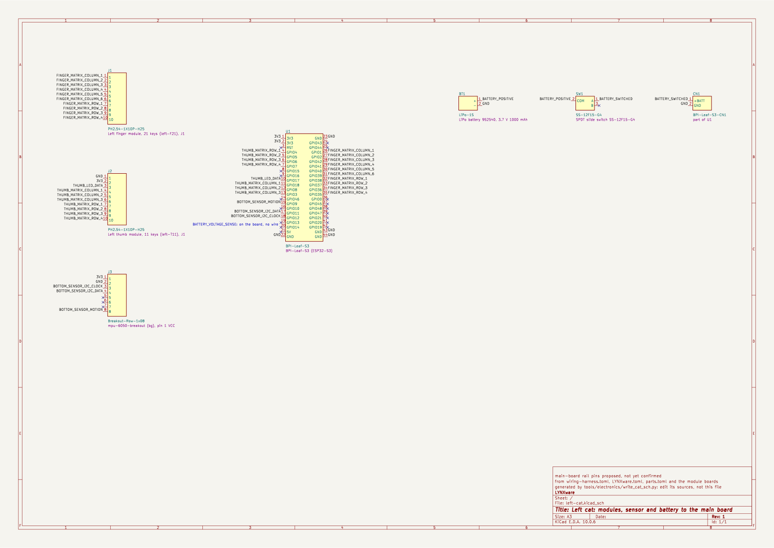
Schematic of the left cat
The whole hand in one KiCad schematic: the main board, each module's header or sensor breakout, and the
battery through its switch to CN1. Opens full size in a new tab.
Right cat
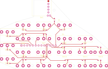
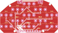
Right finger module, 20 keys + scroll wheel → main board
Right finger module, 20 keys + scroll wheel right-F20W in review
Its header J1 (KH-2.54PH180-1X13P-L11.5 (LCSC C2932703), 1×13 vertical 2.54 mm, bottom side) stands out of the board's bottom; the drawing
shows the bottom face, ▪ marks pin 1. The board's page
- The cable is not measured yet: its kind, length and where each end is soldered are unknown.
- The main-board pins of the rails (GND) are lynx-v4's proposal: no cat has been wired this way yet.
The main board's pins are measured off Banana Pi's dimension drawing (bpi_leaf_s3_board_board_dimension.jpg), which dimensions none of them; not yet measured on a board, ±0.1 mm.
- ground
- scroll encoder
- key matrix
| Header pin | Signal | Main-board pin | Row · position | What it carries |
|---|---|---|---|---|
| J1·1 | GND | GND pin 23 proposal | J3·1 | ground — LED return, encoder common, sensor ground |
| J1·2 | WA | GPIO43 pin 24 | J3·2 | scroll encoder channel A, input, pull-up — EVQWGD001; fkw only |
| J1·3 | WB | GPIO44 pin 25 | J3·3 | scroll encoder channel B, input, pull-up — EVQWGD001; fkw only |
| J1·4 | FO1 | GPIO1 pin 26 | J3·4 | matrix column 1 (firmware column 0), output — driven low to scan; index · outer |
| J1·5 | FO2 | GPIO2 pin 27 | J3·5 | matrix column 2 (firmware column 1), output — index · inner |
| J1·6 | FO3 | GPIO42 pin 28 | J3·6 | matrix column 3 (firmware column 2), output — middle; the left board's m0 is on column 1 |
| J1·7 | FO4 | GPIO41 pin 29 | J3·7 | matrix column 4 (firmware column 3), output — ring |
| J1·8 | FO5 | GPIO40 pin 30 | J3·8 | matrix column 5 (firmware column 4), output — pinky · inner |
| J1·9 | FO6 | GPIO39 pin 31 | J3·9 | matrix column 6 (firmware column 5), output — pinky · outer |
| J1·10 | FI1 | GPIO38 pin 32 | J3·10 | matrix row 1 (firmware row 0), input, pull-up — physical bottom row |
| J1·11 | FI2 | GPIO37 pin 33 | J3·11 | matrix row 2 (firmware row 1), input, pull-up |
| J1·12 | FI3 | GPIO36 pin 34 | J3·12 | matrix row 3 (firmware row 2), input, pull-up |
| J1·13 | FI4 | GPIO35 pin 35 | J3·13 | matrix row 4 (firmware row 3), input, pull-up — physical top row |
Right thumb module, 11 keys → main board
Right thumb module, 11 keys right-T11 qualified
Its header J1 (A2541WV-10P (LCSC C225485), 1×10 vertical 2.54 mm, bottom side) stands out of the board's bottom; the drawing
shows the bottom face, ▪ marks pin 1. The board's page
- The cable is not measured yet: its kind, length and where each end is soldered are unknown.
- The main-board pins of the rails (3V3, GND) are lynx-v4's proposal: no cat has been wired this way yet.
The main board's pins are measured off Banana Pi's dimension drawing (bpi_leaf_s3_board_board_dimension.jpg), which dimensions none of them; not yet measured on a board, ±0.1 mm.
- key matrix
- LED data
- supply
- ground
| Header pin | Signal | Main-board pin | Row · position | What it carries |
|---|---|---|---|---|
| J1·1 | TI4 | GPIO7 pin 7 | J1·7 | matrix row 4 (firmware row 3), input, pull-up; `tk` only — physical top row |
| J1·2 | TI3 | GPIO6 pin 6 | J1·6 | matrix row 3 (firmware row 2), input, pull-up |
| J1·3 | TI2 | GPIO5 pin 5 | J1·5 | matrix row 2 (firmware row 1), input, pull-up; `tk` only — the joystick thumb (tkj) has no keys on rows 2 and 4: its stick's axes take their pins |
| J1·4 | TI1 | GPIO4 pin 4 | J1·4 | matrix row 1 (firmware row 0), input, pull-up — physical bottom row |
| J1·5 | TO3 | GPIO3 pin 13 | J1·13 | matrix column 3 (firmware column 2), output — arc positions 4–5: PCB columns d, e |
| J1·6 | TO2 | GPIO8 pin 12 | J1·12 | matrix column 2 (firmware column 1), output — arc position 3: PCB column c, with the center key |
| J1·7 | TO1 | GPIO18 pin 11 | J1·11 | matrix column 1 (firmware column 0), output — arc positions 1–2: PCB columns a, b |
| J1·8 | LED_DATA | GPIO17 pin 10 | J1·10 | LED data, output — WS2812-protocol data to LED1 DIN (RMT channel 0) |
| J1·9 | 3V3 | 3V3 pin 1 proposal | J1·1 | 3.3 V rail — supply of the thumbs' LEDs, the joystick thumb's stick and the bottom slot's sensor breakout (no GPIO can source it) |
| J1·10 | GND | GND pin 44 proposal | J3·22 | ground — LED return, encoder common, sensor ground |
Bottom module, mouse sensor PMW3389 → main board
Bottom module, mouse sensor PMW3389 BM-PMW3389 qualified
A purchased PMW3389 motion sensor breakout, wired lead by lead. Its pins are drawn in its own row, from pin 1 (▪), each with the name printed beside it. The row is read from the sellers' product photos on Tindie: one row, pin 1 the square pad at VIN (citizenjoe/pmw3389-motion-sensor); the original JACK Enterprises board has the same order, labelled VI, MI, MO, SC, SS, MT, GD, RS (jkicklighter/pmw3389-motion-sensor). The pitch is not stated.
- The cable is not measured yet: its kind, length and where each end is soldered are unknown.
- The main-board pins of the rails (3V3, GND) are lynx-v4's proposal: no cat has been wired this way yet.
The main board's pins are measured off Banana Pi's dimension drawing (bpi_leaf_s3_board_board_dimension.jpg), which dimensions none of them; not yet measured on a board, ±0.1 mm.
- SPI
- interrupt
- reset
- supply
- ground
| Lead | Signal | Main-board pin | Row · position | What it carries |
|---|---|---|---|---|
| SCLK pin 4, “SCK” | SCLK | GPIO12 pin 18 | J1·18 | sensor SPI SCLK, output; `bm-pmw3389`, `bm-pmw3610` only — SPI2 clock, idle high |
| MOSI pin 3, “MOSI” | MOSI | GPIO11 pin 17 | J1·17 | sensor SPI MOSI, output; `bm-pmw3389`, `bm-pmw3610` only — SPI2 data out; the PMW3610's one half-duplex data line (SDIO) is this pin, then also an input |
| MISO pin 2, “MISO” | MISO | GPIO13 pin 19 | J1·19 | sensor SPI MISO, input; `bm-pmw3389` only — SPI2 data in |
| NCS pin 5, “SS” | NCS | GPIO10 pin 16 | J1·16 | sensor SPI NCS, output; `bm-pmw3389`, `bm-pmw3610` only — chip select, driven by software, idle high |
| MOTION pin 6, “MT” | MOTION | GPIO9 pin 15 | J1·15 | sensor interrupt, input, pull-up — active low: motion or data to read; wakes the sensor task. The gyro's INT, which its driver sets active low |
| NRESET pin 8, “RST” | NRESET | GPIO46 pin 14 | J1·14 | sensor reset, output; `bm-pmw3389` only — active low, idle high; a boot strap (Strapping pins) ⚠ Boot strap: with a PMW3389 fitted, the BOOT-button download may fail; disconnect the sensor's NRESET lead for the download. not bench-verified |
| VDDIO pin 1, “VIN” | 3V3 | 3V3 pin 2 proposal | J1·2 | 3.3 V rail — supply of the thumbs' LEDs, the joystick thumb's stick and the bottom slot's sensor breakout (no GPIO can source it) |
| GND pin 7, “GND” | GND | GND pin 22 proposal | J1·22 | ground — LED return, encoder common, sensor ground |
Battery → main board
The LiPo battery 952540, 3.7 V 1000 mAh plugs its own lead, ending in a 2-pin JST 1.25 mm, into the main board's socket CN1, a 2-pin MX 1.25 mm on the board's top side. Its + conductor runs
through the SPDT slide switch SS-12F15-G4 on the way.
Measure the plug before connecting it. Its polarity is not verified (which plug contact is +: MakerFocus does not publish it; measure before plugging in). The socket's + is contact 1.
- The lead is not measured yet: its kind and length are unknown.
- Switch: LCSC rates it 300 mA at 5 V, below the Leaf-S3's 500 mA charge current: check the datasheet's carry rating, or choose a switch rated for it.
The socket's contacts and position are from Banana Pi's schematic (contacts) and dimension drawing (position), measured off the drawing, ±0.3 mm; the switch's pins are 4.7 mm apart (the pin pitch measured by Stas (2026-09-29); body 19.5 × 5.6 mm (LCSC C698212)). The rest is placed schematically; ▪ marks pin 1 and contact 1.
| Lead | Conductor | From | To |
|---|---|---|---|
| + (positive) | red | Battery + | Switch pin 2 (common) |
| + (positive) | red | Switch pin 1 (throw) | CN1 contact 1 |
| − (negative) | black | Battery − | CN1 contact 2 |
LiPo battery 952540, 3.7 V 1000 mAh. One 3.7 V 1000 mAh (3.7 Wh) cell with its own protection board and a 2-pin JST 1.25 mm plug, which fits the main board's MX 1.25 mm socket, + on its pin 1 (electronics/wiring-harness.toml [main_board.battery]). Its size is the Blender model's (mechanical/associations.toml). The BPI-Leaf-S3 charges at 500 mA (Banana Pi's wiki), exactly the cell's 0.5C maximum charge current (MakerFocus's page); any replacement cell needs 1000 mAh or more for the same margin. Sold in packs of four.
SPDT slide switch SS-12F15-G4. Three solder pins, the middle one common; the + lead uses the common and one outer pin, the other stays open. Body 19.5 × 5.6 mm (LCSC), panel ears with Ø2.5 mm holes 15 mm apart (BC Robotics), held by the lid's Lid-Switch-Holder. Off, it also cuts the charger: the Leaf-S3 charges the cell through the same socket, so the battery charges only while the switch is on.
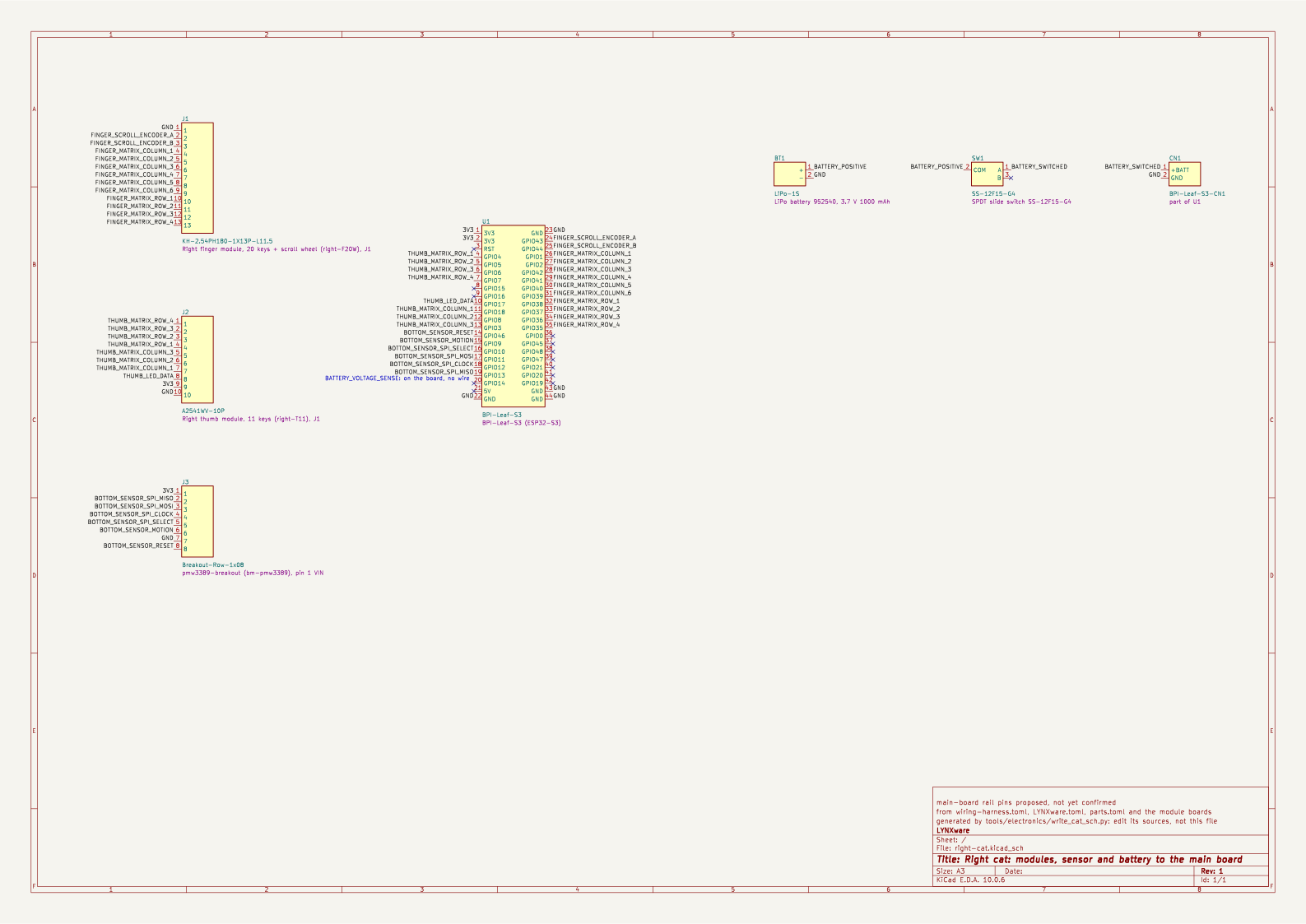
Schematic of the right cat
The whole hand in one KiCad schematic: the main board, each module's header or sensor breakout, and the
battery through its switch to CN1. Opens full size in a new tab.
Breakouts
A sensor breakout, purchased or a board of LYNX's own, is wired lead by lead, the same on either hand, whether the reference build fits it or not.
- bottom Bottom module, gyro MPU-6050 breakout, GY-521, 5 wires
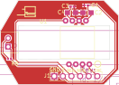 bottom Bottom module, mouse sensor ADNS-5050 ADNS-5050 mouse module (v3), 6 wires
- bottom Bottom module, mouse sensor PMW3389 PMW3389 motion sensor breakout, 8 wires
- bottom Bottom module, mouse sensor PMW3610 PMW3610 breakout board, 6 wires
Bottom module, gyro → main board
- The sensor of the gyro bottom module: the hand as an air mouse.
- The reference build fits it: Left cat, bottom.
- Still open: run the driver on a fitted gyro (variant BG); caliper a real board against the drawn one.
Bottom module, gyro BG planned
A purchased MPU-6050 breakout, GY-521, wired lead by lead. Its pins are drawn in its own row, from pin 1 (▪), each with the name printed beside it, 2.54 mm apart. The row is read from Fritzing's GY-521 part (fritzing-parts, core/InvenSense_MPU6050.fzp; the board gyro_ref.py draws): one row, pin 1 VCC, the order of the board's silkscreen. XDA and XCL (the MPU-6050's auxiliary I2C) and AD0 stay open.
- The cable is not measured yet: its kind, length and where each end is soldered are unknown.
- The main-board pins of the rails (3V3, GND) are lynx-v4's proposal: no cat has been wired this way yet.
The main board's pins are measured off Banana Pi's dimension drawing (bpi_leaf_s3_board_board_dimension.jpg), which dimensions none of them; not yet measured on a board, ±0.1 mm.
- I2C
- interrupt
- supply
- ground
| Lead | Signal | Main-board pin | Row · position | What it carries |
|---|---|---|---|---|
| SDA pin 4, “SDA” | SDA | GPIO11 pin 17 | J1·17 | sensor I2C SDA, bidirectional; `bg` only — I2C0 data, open drain; the breakout's own pull-ups hold it high |
| SCL pin 3, “SCL” | SCL | GPIO12 pin 18 | J1·18 | sensor I2C SCL, output; `bg` only — I2C0 clock, open drain; the breakout's own pull-ups hold it high |
| INT pin 8, “INT” | MOTION | GPIO9 pin 15 | J1·15 | sensor interrupt, input, pull-up — active low: motion or data to read; wakes the sensor task. The gyro's INT, which its driver sets active low |
| VCC pin 1, “VCC” | 3V3 | 3V3 pin 2 proposal | J1·2 | 3.3 V rail — supply of the thumbs' LEDs, the joystick thumb's stick and the bottom slot's sensor breakout (no GPIO can source it) |
| GND pin 2, “GND” | GND | GND pin 22 proposal | J1·22 | ground — LED return, encoder common, sensor ground |
Bottom module, mouse sensor ADNS-5050 → main board
- The bottom module BM-ADNS5050: LYNX's own board with the ADNS-5050 sensor and its LED; runs from USB's 5 V only.
- The reference build fits it on no hand.
- Still open: the ADNS-5050 itself is discontinued: a source for the sensor.
Bottom module, mouse sensor ADNS-5050 BM-ADNS5050 in review
The ADNS-5050 mouse module (v3), a board of LYNX's own, wired lead by lead. Its pins are drawn in its own row, from pin 1 (▪), each with the name printed beside it, 2.54 mm apart. The row is read from the v3 board (EasyEDA PCB_PCB_adns5050, 2026-10-16), header H1: pin 1 the square pad, its nets and the silkscreen beside each pin; electronics/boards/bottom-module-mouse-sensor-adns5050 draws it 1:1, the header as J1. The board's page
- The cable is not measured yet: its kind, length and where each end is soldered are unknown.
- The main-board pins of the rails (5V, GND) are lynx-v4's proposal: no cat has been wired this way yet.
The main board's pins are measured off Banana Pi's dimension drawing (bpi_leaf_s3_board_board_dimension.jpg), which dimensions none of them; not yet measured on a board, ±0.1 mm.
- SPI
- reset
- supply
- ground
| Lead | Signal | Main-board pin | Row · position | What it carries |
|---|---|---|---|---|
| SCLK pin 3, “sclk” | sclk | GPIO14 pin 20 | J1·20 | sensor SPI SCLK, output; `bm-adns5050` only — SPI2 clock, idle high; v3's pin, main-board pin 20. The main board's battery divider (470 kΩ / 470 kΩ) hangs on it: the module never has a battery |
| SDIO pin 4, “sdio” | sdio | GPIO13 pin 19 | J1·19 | sensor SPI MOSI, bidirectional; `bm-adns5050` only — the one half-duplex data line (SDIO), SPI2 SIO0; v3's pin, main-board pin 19 |
| NCS pin 6, “nsc” | nsc | GPIO11 pin 17 | J1·17 | sensor SPI NCS, output; `bm-adns5050` only — NCS, driven by software, idle high; v3's pin, main-board pin 17 |
| NRESET pin 5, “n” | n | GPIO12 pin 18 | J1·18 | sensor reset, output; `bm-adns5050` only — NRESET, active low, idle high; v3's pin, main-board pin 18 |
| VDD5 pin 2, “V” | 5V | 5V pin 21 proposal | J1·21 | 5 V rail; `bm-adns5050` only — the main board's USB VBUS: live only while USB is plugged in, never from the battery; supply of the ADNS-5050 module alone, so its hand has no battery (build.toml [[rule]] battery-not-with-usb-only-sensor) |
| GND pin 1, “GND” | GND | GND pin 22 proposal | J1·22 | ground — LED return, encoder common, sensor ground |
Bottom module, mouse sensor PMW3389 → main board
- The sensor of the bottom module BM-PMW3389, with its lens; runs from the 3.3 V rail.
- The reference build fits it: Right cat, bottom.
- Still open: Sold out on Tindie since 2026-08-27 (seen 2026-09-27); the listing points to the seller's Lectronz shop.
Bottom module, mouse sensor PMW3389 BM-PMW3389 qualified
A purchased PMW3389 motion sensor breakout, wired lead by lead. Its pins are drawn in its own row, from pin 1 (▪), each with the name printed beside it. The row is read from the sellers' product photos on Tindie: one row, pin 1 the square pad at VIN (citizenjoe/pmw3389-motion-sensor); the original JACK Enterprises board has the same order, labelled VI, MI, MO, SC, SS, MT, GD, RS (jkicklighter/pmw3389-motion-sensor). The pitch is not stated.
- The cable is not measured yet: its kind, length and where each end is soldered are unknown.
- The main-board pins of the rails (3V3, GND) are lynx-v4's proposal: no cat has been wired this way yet.
The main board's pins are measured off Banana Pi's dimension drawing (bpi_leaf_s3_board_board_dimension.jpg), which dimensions none of them; not yet measured on a board, ±0.1 mm.
- SPI
- interrupt
- reset
- supply
- ground
| Lead | Signal | Main-board pin | Row · position | What it carries |
|---|---|---|---|---|
| SCLK pin 4, “SCK” | SCLK | GPIO12 pin 18 | J1·18 | sensor SPI SCLK, output; `bm-pmw3389`, `bm-pmw3610` only — SPI2 clock, idle high |
| MOSI pin 3, “MOSI” | MOSI | GPIO11 pin 17 | J1·17 | sensor SPI MOSI, output; `bm-pmw3389`, `bm-pmw3610` only — SPI2 data out; the PMW3610's one half-duplex data line (SDIO) is this pin, then also an input |
| MISO pin 2, “MISO” | MISO | GPIO13 pin 19 | J1·19 | sensor SPI MISO, input; `bm-pmw3389` only — SPI2 data in |
| NCS pin 5, “SS” | NCS | GPIO10 pin 16 | J1·16 | sensor SPI NCS, output; `bm-pmw3389`, `bm-pmw3610` only — chip select, driven by software, idle high |
| MOTION pin 6, “MT” | MOTION | GPIO9 pin 15 | J1·15 | sensor interrupt, input, pull-up — active low: motion or data to read; wakes the sensor task. The gyro's INT, which its driver sets active low |
| NRESET pin 8, “RST” | NRESET | GPIO46 pin 14 | J1·14 | sensor reset, output; `bm-pmw3389` only — active low, idle high; a boot strap (Strapping pins) ⚠ Boot strap: with a PMW3389 fitted, the BOOT-button download may fail; disconnect the sensor's NRESET lead for the download. not bench-verified |
| VDDIO pin 1, “VIN” | 3V3 | 3V3 pin 2 proposal | J1·2 | 3.3 V rail — supply of the thumbs' LEDs, the joystick thumb's stick and the bottom slot's sensor breakout (no GPIO can source it) |
| GND pin 7, “GND” | GND | GND pin 22 proposal | J1·22 | ground — LED return, encoder common, sensor ground |
Bottom module, mouse sensor PMW3610 → main board
- The sensor of the bottom module BM-PMW3610 (planned); needs no SROM.
- The reference build fits it on no hand.
- Still open: bench test: which revision randware ships, lens height. Its breakout (23.5 x 31.5 mm) fits no pocket of the mouse lid: it needs a smaller breakout or a lid of its own (mechanical/dimensions.json bottom_module open).
Bottom module, mouse sensor PMW3610 BM-PMW3610 planned
A purchased PMW3610 breakout board, wired lead by lead. Its pins are drawn in its own row, from pin 1 (▪), each with the name printed beside it, 2.54 mm apart. The row is read from siderakb's pmw3610-pcb rev 2.1 (github.com/siderakb/pmw3610-pcb, J1 1×7): the design randware builds, its shipped revision unconfirmed. RST (the sensor's NRESET) stays open: the driver does not wire it.
- The cable is not measured yet: its kind, length and where each end is soldered are unknown.
- The main-board pins of the rails (3V3, GND) are lynx-v4's proposal: no cat has been wired this way yet.
The main board's pins are measured off Banana Pi's dimension drawing (bpi_leaf_s3_board_board_dimension.jpg), which dimensions none of them; not yet measured on a board, ±0.1 mm.
- SPI
- interrupt
- supply
- ground
| Lead | Signal | Main-board pin | Row · position | What it carries |
|---|---|---|---|---|
| SCLK pin 4, “SCLK” | SCLK | GPIO12 pin 18 | J1·18 | sensor SPI SCLK, output; `bm-pmw3389`, `bm-pmw3610` only — SPI2 clock, idle high |
| SDIO pin 3, “SDIO” | MOSI | GPIO11 pin 17 | J1·17 | sensor SPI MOSI, output; `bm-pmw3389`, `bm-pmw3610` only — SPI2 data out; the PMW3610's one half-duplex data line (SDIO) is this pin, then also an input |
| NCS pin 5, “CS” | NCS | GPIO10 pin 16 | J1·16 | sensor SPI NCS, output; `bm-pmw3389`, `bm-pmw3610` only — chip select, driven by software, idle high |
| MOT pin 6, “MOT” | MOTION | GPIO9 pin 15 | J1·15 | sensor interrupt, input, pull-up — active low: motion or data to read; wakes the sensor task. The gyro's INT, which its driver sets active low |
| VDD pin 1, “VIN” | 3V3 | 3V3 pin 2 proposal | J1·2 | 3.3 V rail — supply of the thumbs' LEDs, the joystick thumb's stick and the bottom slot's sensor breakout (no GPIO can source it) |
| GND pin 2, “GND” | GND | GND pin 22 proposal | J1·22 | ground — LED return, encoder common, sensor ground |