Blender files
Edit a linked part in its own .blend file; keep library paths relative and inside this
repository.
| File | Ownership |
|---|---|
| key.blend | Keycap in three variants on one notch and footprint: the keycap, with a dished top; the anchor keycap, the keycap's finished geometry plus Key-Cap-Anchor-Bar; the hump keycap, 1.8 mm taller with a domed top. The modules seat on each key the cap build.toml gives it (keys): the anchor keycap on the home keys (LYNXware.toml home), the hump keycap on the keys it lists, the keycap on the others. Also the master key cutout |
| finger-module.blend | Finger module covers (left, and its right twin), key grid, envelope, mounting screws, both finger boards placed, a keycap on every key; links key and references |
| thumb-module.blend | Thumb module covers (left, and its right twin), the translucent LED plug, envelope, mounting screws, both thumb boards placed, a keycap on every key and a plug in every LED window; the joystick thumb's cover, dome and cap (the joystick thumb); links key and references |
| lid.blend | Lid in four variants, one per kind of bottom slot, all built from Lid-Plate (the lid without feet, bottom module or battery), and the first three each with and without the battery (the battery and the power switch): plain with rubber pads (no bottom module), gyro with the GY-521's pocket and pads, mouse with the sensor breakout's pocket, a window under the lens and PTFE skates (it slides the hand on the desk; mechanical/associations.toml bottom), and the v3 ADNS-5050 module's mouse lid, its own holder with the board snapped into a pocket, and skates, always without the battery; left, and their right twins; the bottom modules themselves, which have no printed part of their own: the holder, each module's cuts and the breakout where it sits (the bottom module); its envelope and casing/lid screw system, a foot's pocket over every screw holding its head (the lid's feet); the plate outline is drawn by hand, and the envelope, the screw places and the casing's lower edge are written from it (the casing rim), and so is the space the casing leaves the holders (the lid's space); links references |
| casing.blend | Casing (left, and its right twin) and slot placement, flush with its modules, with the slots shown where it cuts them (the casing's slots) and the lid where it sits (the lid's space); links the finger and thumb module files and lid |
| references.blend | The boards' KiCad geometry, one collection per board, and measured, drawn or missing purchased modules and screws, with provenance/status tags |
| scene/cat.blend | The Assembly assembled: places the fitted parts (./lx mech assemble); retains Logo, the logo artwork Logo-Cut, which cuts no part yet |
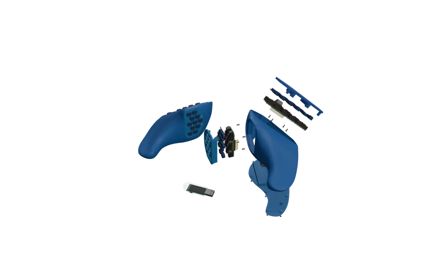
The inserted part owns its shape and fasteners; the receiving part owns placement. Envelopes live beside the variants whose shape defines them. Links flow from key and references to modules to casing to scene; modules do not link one another. Do not make linked geometry local or bake copies into source parts. Export evaluated copies for slicing (exports).
associations.toml owns cross-domain relationships;
dimensions.json owns fit requirements and unresolved dimensional
conflicts. Presentation and visibility are authored in scene/; generated
renders are not sources. Names put the side first (namings). A module's
parts carry its stem from LYNXware.toml: left-finger-module-21-keys-cover,
…-board (the imported board), …-board-placement, …-keycaps-placement,
…-led-plugs-placement; other side-specific parts and
containers read left-casing-body, right-finger-module. Shared helpers without a side
keep their names (Finger-Key-Grid, Finger-Envelope). The generated
module lookup lists each module's file and parts. Older
names and the rename commits: namings.
Collections
A file shows its sets at the top level; the file already says what they belong to. First
come the parts, the left ones, their right twins, then the rest: left-lid-plain,
left-lid-gyro, left-lid-mouse, left-lid-mouse-adns5050, left-lid-plain-no-battery, …, right-lid-plain, …,
Thumb-LED-Plug. A part set holds only its printed part (left-finger-module: the cover).
What is placed under the part from other sets sits beside it in its imports set,
<set>-imports: a module's board, the keycaps and LED plugs its cover takes, the mouse
lid's sensor breakout, the screws each part takes and the gyro's washers (left-finger-module-imports, left-lid-mouse-imports; place_boards.py,
place_cover_parts.py, ./lx mech cover-parts;
place_screws.py, ./lx mech screws). The
scene places both. Everything else sits in sets named <Prefix>-<What>, whose Outliner color
says what their objects do to the part:
| Color | Function | Shown by default |
|---|---|---|
| blue | parts: left, right twins, variants | yes |
| red | cuts | no |
| green | unions | no |
| violet | contracts other files are built against (envelopes, Key-Cutout, Lid-Screws) | yes |
| yellow | helpers: placement empties, origins, templates | no |
| orange | references: context only, shaping no part, shown to see where things are and how they come together: a part's placed imports (left-finger-module-imports), boards and drawn references, the lid's space (Lid-Space), the lid on the casing (Casing-Lid-Preview); also the sets objects are linked into (Casing-linked), whose objects keep their own file's color | yes |
| brown | test prints | no |
| pink | unused: no modifier uses it, kept until decided | no |
| none | a feature group mixing functions (Lid-Switch, Thumb-LED) | no |
The part files draw every face in the color of the set it comes from (./lx mech colors,
colors.py): a finished part shows its body blue, what a cut
removed red, what an envelope or Key-Cutout cut violet, what a union added green, and the
right twins the same grayed. The printed parts a module's cover takes, keycaps and LED plugs,
draw one gray in the module file: their placements instance a <source>-print stand-in that
realizes the part in that gray (Cover-Print), while the file modelling them paints them as
parts. The paint is the color attribute function, which booleans
and geometry nodes carry onto the result; materials stay what renders and exports show. An
object in an untagged set is painted by how the booleans use it, or, when parts only take its
geometry (Lid-Plate), like those parts. After adding an object,
run ./lx mech colors; ./lx mech check fails until then, and also when a part set holds
anything but meshes.
Each part file says what its colors mean where it opens: the set Legend, last at the top
level, lies flat (read from above) left of the parts, a swatch per color with its meaning. ./lx mech colors draws
it from colors.py's LEGEND_LINES, the same in every file; it cannot be selected, and nothing
places or exports it. Hide it with its eye. The scene draws materials and has none.
A set a boolean takes as its collection operand holds exactly that operand, children included, so nest nothing else in it. Other files link the part sets and what the violet sets hold by name.
Booleans use the Manifold solver, modifiers and Mesh Boolean nodes alike: 10–20 times faster than
Exact, so parts stay live while edited, and its results are closed. A new Boolean modifier starts
on Exact; switch it. Manifold needs closed operands: given one with an open edge it skips the
cut, with only a warning on the modifier ("non-manifold geometry"), and ./lx mech check fails on
the part's faces or volume. Faces not flat are split along a diagonal each solver picks itself,
so where that shapes a part, triangulate the operand (Casing-Volume-Cut).
The scene
scene/cat.blend holds no part geometry. ./lx mech assemble
(assemble.py) places, per hand, what
LYNXware.toml fits: the casing, the lid the bottom slot and the battery ask for
(associations.toml bottom, battery) with the bottom module it holds, the finger and thumb modules with
their boards, the battery and its power switch where the side has one, the main board, and once
the tower.
Each placement records whose it is (device, side), which the website's nodes carry. Each placement is an empty that
instances a part set, and a second one its imports set where it has one, so the part is
evaluated in its own file with every cutter and then moved as a whole. The receiving part owns the place: the casing's Casing-Finger-Slot-Pos and
Casing-Thumb-Slot-Pos (where it cuts the module openings), the lid's Lid-Board-Pos,
Lid-Switch-Pos and Lid-Battery-Pos; a right module sits at the left slot's mirror image. The keycaps and LED
plugs come with their module: each cap sits in its key cutout at key.blend's modelled height, which is not yet where it
rests on its switch (the keycap pocket, open issues). After moving
a slot, the board or the switch, or changing the Assembly, run ./lx mech assemble; ./lx mech check
fails until then. What the website gets of the scene, one node per selectable part and each
view per hand, is scene_roots.py's. The scene's sets are grouped as the explosion views move them
(views.json); visibility.json
records its flags.
The main board, the power switch and the tower
No maker publishes a model we may redistribute, so all three are drawn
(status = "drawn" in references.blend) from the published outline and the product photos, in
their real colors as materials: recognizable, not fit-approved. Where a part sits and how big it is
beyond the outline is read off photos and usual packages
(ref_shapes.py holds the shapes and the palette).
The cat's main board is a BPI-Leaf-S3 with its header pins soldered pointing up
(main_board_ref.py, References-Main-Board). Its outline,
holes and pins are the KiCad part's (footprints.toml
BPI-Leaf-S3, through wires.py), and the scene export
fails when a pin the wiring harness wires is not drawn where that part has it. The scene
seats it in the lid's board holder: antenna end against the holder's end wall, on the floor of
the grooves it slides in, USB-C at the open end. assemble.py reads the seat off
Lid-Board-Groove-Cut, so moving the holder moves the board. It sits as low as its USB cable
allows: the casing keeps 3 mm under the cable's opening, over the lid seat
(dimensions.json main_board; its underside 6.3 mm over the lid's face, 7.9 mm
lower since the bottom module moved beside it). Drawn this way, its pin tails
touch the holder's floor (0.05 mm) and its header strips the lip above the grooves (0.1 mm);
the jumper wires on the pins are not modelled. Its battery socket (CN1) is drawn where the wiring
harness puts it ([main_board.battery]), open toward the side the plug enters, and the scene
export anchors the battery wires at its contacts.
The power switch is the SS-12F15-G4 slide switch on the battery's + lead
(power_switch_ref.py, References-Power-Switch; its
docstring separates the sourced dimensions from the eyeballed ones). Its pins are at the
harness's pitch. The lid's Lid-Switch-Pos seats it in the holder beside the main board's left
edge, about its middle and parallel to it, the holder merged with the board holder's rail (since
2026-10-06): its plate on the floor of the pocket Lid-Switch-Cut cuts, actuator down through the
lid's floor, pins up, pin 1's end towards the main board's socket. The holder and the cut are the
helper's children, so they move with it; the cut is symmetric, so the helper owns which way pin 1
points (turning it half a turn about its z changes no geometry), and assemble.py fails when the
cut leaves the helper's centre, floor or long axis. The
right switch is the left one turned about its length, which keeps pin 1 at the socket's end. The
battery (References-Battery) is the hand-measured Lid-Battery-ref, the size authority, drawn in
its own frame (the middle of its underside on the origin, +y toward its leads; the lid's
Lid-Battery-Pos seats it, its two holders the helper's children, since 2026-10-08), with
where its lead leaves the cell, eyeballed
(battery_lead_ref.py): red and black stubs whose ends
are empties naming the lead's conductor, which the scene export anchors the battery's wires at.
The tower is a LILYGO T-Dongle-S3 (LYNXware.toml [tower]), which ships in
its own clear shell: LYNX prints no enclosure for it. It is drawn as it is plugged in, without
its cap (tower_ref.py, References-Tower). With a BPI-Leaf-S3
tower ([tower] board), the scene lays the main board's set where the dongle would lie, USB-C to
the right.
The battery and the power switch
A cat may run without a battery, from its USB cable to the computer or a USB power supply
(build.toml [choice.battery]); it then fits no power switch either. So each lid but the
ADNS-5050's comes twice: built on Lid-Plate-Battery (Lid-Plate with the switch's holder, its
pocket and window through the floor, and the battery's two holders), or as -no-battery on
Lid-Plate itself, the floor closed where the window would be and nothing to hold what is not
fitted. The ADNS-5050's lid is only the latter: that sensor runs from the main board's 5 V pin,
which only USB powers (build.toml rule battery-not-with-usb-only-sensor). Lid-Plate-Battery
takes Lid-Plate's finished geometry (Geometry-From) and adds them after the screws: the screws
neither reach the switch nor the holders, so the battery lids kept every vertex; only a few
faces not quite flat split along other diagonals. A lid without a battery shares its sibling's
imports: one placement of a bottom module's breakout and its screws sits in both lids' imports
sets. ./lx mech check fails when a lid's lid plate starts from another plate than its
battery says (check_associations.py).
The casing rim
The ring of casing around the lid is 2.1 mm wide all round where the slicer cuts the first layer,
0.1 mm over the bed, so Bambu Studio lays 4 walls there (dimensions.json
casing_rim). Its P2S profiles print the first layer in 0.5 mm lines and shrink it by 0.15 mm of
elephant-foot compensation: the ring of 4 × 0.4 mm it had before printed 3 lines. The lid owns that
shape since 2026-10-10; the casing follows it. Draw the outline on Lid-Plate's base mesh, which
every lid variant is built from: move its side faces, keep its thickness. ./lx mech lid-fit
(lid_fit.py, geometry in rim.py) cuts
the plate halfway up, grows it by the lid's clearance (0.08 mm a side, 0.12 until the first print
moved too much) into the seat, and writes into lid.blend Lid-Envelope (the seat, and above the
plate its step, reaching over the lid's screw bosses) and each Lid-Screw-N-Pos: a fixed distance inside
the seat, facing across the rim, where it already sits along it, with its foot (the lid's feet).
The seat grown by the rim is where the casing's outer surface must cut the first layer; the fairing
below puts it there.
To move a screw, move its empty along the rim and run it again. There are eight (fastener.casing_lid_screws
count), placed since 2026-10-08 under the skates as Stas arranged them for the mouse lid; each pad sits
over its screw as well. Two of them sit where the casing leaves little room: screws 5 and 6 beside the finger
module's opening, which trims 2.8 and 0.7 mm³ off their casing bosses (FINDINGs: the opening wins, the
holes keep 0.7 and 0.9 mm), and screw 8 under the board's stopper at the USB end, threading into it, its
its hole as long as the others', its top about 0.27 mm under the cable's opening. A screw
whose bosses or hole reach into the board, the battery, the switch, the bottom module, a holder or a module's
envelope is a FINDING; the casing's USB cuts and the stopper it does not see, so keep a screw moved near them
clear by eye. A finished casing in more than one piece fails: a casing boss reaches 0.6 mm past its old outer
face along its slope, since on the waist the casing's cavity thins the wall and screw 3's boss once missed it. After reshaping the lid plate or the casing run it; ./lx mech check fails until
then, and whenever the finished casings' rim leaves 2.1 mm there. Only that height is exact: the
casing's lower edge flares out, so the ring widens above it.
lid-fit fairs that edge first (rim_fair.py, casing_rim.fair). The
casing is drawn as a tilted cage, so the bed cuts its faces at a slant: the outline on the bed
rippled at the cage's spacing and the flare jumped along the rim. Casing-Rim-Fair, the modifier
after Casing-Slot-Conform, moves the surface sideways onto the lid's outline, the flare evened
along the rim (its mean kept, so the wall still leans out as drawn): wholly up to 0.5 mm over the
bed, fading to nothing at 3 mm, the surface as drawn above. lid-fit measures the shifts on the
casing as drawn and stores them in Casing-Rim-Fair-Field (Casing-Helpers, hidden), so the cage
stays yours: reshape it, then run lid-fit. The casing's Subdivision is level 3 for it: at level 2
the chords of its facets near the bed rippled the edge by themselves.
The casing's Triangulate right after Subdivision belongs to the rim: a subdivided surface's
quads are not flat, and without it every boolean after them splits them along its own diagonal,
moving the printed edge by up to 0.06 mm from what the tool measured.
For the same reason Casing-Volume-Cut has its own Triangulate: its quads are up to 2 mm out
of plane, and the solvers split them differently by 0.8 cm³ of wall. On Manifold the casing
recomputes in about 0.4 s at Subdivision 3 (0.2 s at 2, where Exact took 1.8 s); in Edit Mode it
shows only its surface up to the conform, and the fairing and the cuts follow on leaving it (each
modifier's Edit Mode toggle), so dragging stays live.
The lid's feet
Each foot covers a casing/lid screw: its pocket (Lid-Pads, Lid-Skates) sits over the screw and
holds the head in a smaller pocket, so the pad or skate stuck in it hides the screw
(dimensions.json lid_feet). The lid prints on its outer face, so the pocket,
the head's pocket and the screw's hole open onto the bed one inside the other, and the layer closing
each lies over air with the next opening in it. feet.py draws each
closing as two steps one layer high: a slot as wide as the opening above, across the opening below
from wall to wall, so the strands beside it bridge it anchored at both ends; then, bridged across the
slot, the square the opening above starts from. The lid prints at that layer height (build.toml).
./lx mech lid-fit writes them with the screws: Lid-Pad-N and Lid-Skate-N, a mesh each, seated
on Lid-Screw-N-Pos and cut from the outline of Lid-Screw-Template-Pad or -Skate (beside the
screw template: edit a foot's shape there). A pocket sits offset_mm inward of its screw, its length
along the rim; where the plate's edge bends closer than edge_lines (a skate at the corner of screw 2)
it turns and slides along its length, the head's pocket staying on the screw and inside it. The lid's
boss is a D round the screw that walls the head's pocket. The casing prints on its bottom face, so
its boss grows out of the wall over air: its underside is one slope boss_underside_deg off the bed
(fastener.casing_lid_screws), and the lid boss's top follows it, under the lid clearance.
./lx mech check fails when a foot or a template differs from what the templates and lid_feet
give, or when a casing boss faces the bed flatter than that slope.
The lid's space
The holders are placed in lid.blend against the space the casing leaves them: the
orange set Lid-Space, a reference that shapes and prints nothing. Lid-Space-Casing is the casing's inner volume (its
shell within Casing-Volume-Cut, less what the finished casing holds there: the screw bosses, the board's stopper);
Lid-Space-Finger-Envelope and Lid-Space-Thumb-Envelope, in its violet Lid-Space-Envelopes (an
envelope is a contract wherever it is drawn), are the module envelopes where the casing
cuts their openings. All three are wireframes that cannot be selected, and copies: lid.blend cannot
link the casing back, because the casing links lid.blend (a linked casing loses its seat and
screws). ./lx mech lid-fit writes them with the rim, after reshaping the casing, moving a slot or
changing an envelope; ./lx mech check fails until then.
Lid-Space-Main-Board shows the main board on its seat in the holder (seats.py,
the scene's seat), parented to Lid-Board-Pos: moving it moves the board with its holder, live;
Lid-Space-Power-Switch the power switch on Lid-Switch-Pos, Lid-Space-Battery the battery on
Lid-Battery-Pos, which carries its holders, as the scene seats them; the mouse lid's
imports show its breakout where the lid holds it (the bottom module).
./lx mech lid-fit and its check print a FINDING for the main board, the breakout, the power
switch, the battery or a holder reaching into an envelope or out of the inner volume, for the main board, pin
tails included, or the breakout reaching into the battery holders, the switch's holder or the bottom
module's holder, and for the battery's cell reaching into a holder (its own too), the main board or the
breakout, by the overlap's volume. They see the parts as drawn: not the jumper wires on the
board's header pins nor the wires soldered to the switch's, which stand above the pins towards the
modules. After moving a helper, ./lx mech assemble places the board, the switch and the battery in the scene.
The holders are drawn in their helpers' frames, so a helper carries its holder along; where the
casing or an envelope then cuts into one, its mesh is trimmed by hand (the board holder's ends, cut
for the board's place on 2026-10-06), and a screw whose boss the USB cuts reach moves along the rim
(the casing rim).
The casing's end of the board follows Lid-Board-Pos as well. Casing-Board-Stopper (green) stops the
board at its USB end, and Casing-USB-Cuts (red: Casing-USB-Plug-Cut, Casing-USB-Cable-Cut)
opens the wall for the plug and its cable. The casing's booleans add the stopper right after
the lid cut, so the lid's envelope does not trim it: it reaches down to the seat and touches the
lid near screw 8 (Stas's order since 2026-10-08, open issues);
they cut the USB openings after the screw bosses and holes, so an opening wins over a boss, and the
slot cuts last, so a module's opening wins over all of them. The stopper's own Triangulate keeps its
hand-drawn quads, up to 0.58 mm out of plane, from leaving the casing with n-gons whose split changes
its shape (as Casing-Volume-Cut's does). All three are
parented to Lid-Board-Pos, linked from lid.blend. Once lid.blend is saved, casing.blend
picks up a moved board on its next load (in a running Blender, reload the library).
./lx mech check fails when one of them loses that parent, and when the casing under the
cable's opening is thinner than main_board.usb_wall_mm over the lid seat: the board sits too low.
The other way round, the casing is edited against the lid: casing.blend's orange
Casing-Lid-Preview draws lid.blend's left-lid-mouse-body, finished, where it sits, solid and in
the reference orange in place of its own paint (its node group stores it), and cannot be selected.
It is the lid the left hand fits; the gyro lid differs from it only in the holder's pocket and
underneath, the plain lid by no holder. Only the left one: the right casing
mirrors it. It is linked, so it follows the lid as the seat and the stopper do. ./lx mech lid-fit
draws it where it is missing; ./lx mech check fails when it draws another lid, sits elsewhere, or
evaluates in casing.blend to another shape than lid.blend builds.
The bottom module
A bottom module has no printed part of its own: each kind of bottom slot has its own lid, and the
module's breakout screws into it (dimensions.json bottom_module), so a hand
prints one lid and nothing else. Which way a hand pushes the sensor is the tower's to set: it
turns each hand's motion by the lid's mounting yaw plus the user's trim (firmware
input_engine_rules::motion_yaw, the YL/YR keys in Vial settings),
so nothing turns in the lid, and the main board sits low beside the module.
bottom_module.py (./lx mech bottom-module) builds it in
lid.blend, in the frame of Lid-Bottom-Module-Pos, left of the main board: its origin on the lid's
face, y along the module. The gyro and mouse lids add Lid-Bottom-Module-Holder (green), a block
from inside the plate up to the breakout board's top, and cut their module's set (red, in
Lid-Cuts): Bottom-Gyro-Cuts, the GY-521's pocket, the board flush and 0.2 mm a side, a channel under
its header's row for the pin tails and its two screw holes on the other side (one-sided, so the right
lid holds it turned half round); bottom-module-mouse-sensor-pmw3389-cuts, the
breakout's pocket, flush, its two screw holes, the lens's seat, the room over it up to the board
(a tongue left round each screw) and the window under the lens through the plate, narrowing towards
the face. The lens hangs loose on the chip's guide posts, so the lid holds it as PixArt's base
plate does: its flange rests on the seat's floor, the walls round it stop it moving across, and the
board on its pocket's floor holds it down. The holder and the cuts are children of the
helper, so moving it moves them; each lid takes them right after lid plate in its stack.
The breakout's references (drawn from PixArt's datasheet by
mouse_sensor_ref.py: the board, the chip and the lens)
sit in the mouse lid's imports with the lens flange 2.4 mm over the desk, which lies under the lid's face by what the skates stand proud. The holder and every cut
are symmetric about the helper's x = 0, so the right lid, the left one mirrored, holds the same
breakout turned: its placement in right-lid-mouse-imports is MIRROR · helper · FLIP_X. The
GY-521's references (gyro_ref.py: the board, its parts and its
header, after Fritzing's part and a KiCad redraw) sit in the gyro lid's imports on the pocket's
floor; the gyro's cuts read the pocket, the holes and the header's row off them. Its right
placement is MIRROR · helper · FLIP_X turned half round about z, as its cuts are not symmetric.
The v3 ADNS-5050 module (BM-ADNS5050) has a lid of its own, left-lid-mouse-adns5050-body and its
recipe twin, which bottom_module.py makes from the mouse lid's lid plate and skates where it is
missing. Its board is v3's, 35 × 25 mm without screw holes, so the lid holds it in a pocket 0.25 mm a
side under a lip over the middle of each long edge, 45° under and over; each lip stands on an arm the
lid's slots cut free behind it, at its ends and beside its foot, so it gives as the board snaps in. The
board rests on a ledge at the datasheet's height (its top 7.45 mm over the desk), the lens's flange on a
seat 2.4 mm over the desk, the room between them taking the lens's body and the leads' tails, the
window under the lens round the lens's optics, its prism, the sensor's view and the light's paths
between them, and nothing rising into the board's cutout (dimensions.json
bottom_module adns5050). Its references (adns5050_ref.py: the
board after the v3 EasyEDA board, the stack and the lens's flange and optical centre after Avago's
datasheets, the rest of the discontinued lens after the v3 model) sit in its imports. The board is not
its own mirror image, and its 1×6 header faces the main board in both hands, so the right lid holds it
turned end for end (MIRROR · helper · its place · FLIP_Y), not across as the PMW3389's: each lid has its
own holder (left-/right-bottom-module-mouse-sensor-adns5050-holder, green) and cuts (…-cuts), both
drawn in the left lid's frame, the right ones mirrored with the right lid, a recipe twin that takes them
in place of the left lid's (associations.toml twin_operands, sides.py). Each sits where
bottom_module.py's A_PLACE puts it in the helper, clear of the power switch's pocket (1.5 mm), the
battery (0.3 mm) and the main board's groove (0.13 mm), which the check measures (the lid takes neither
the switch nor the battery, but the module stays where it was test-printed); lid-fit's findings
see both lids' holders and boards.
./lx mech check fails when the holder, a cut, a placement or a lid's stack is stale, the lens
leaves 2.2–2.6 mm over the desk or its seat's floor, the seat leaves it more than 0.15 mm to a
wall, or the window lets light past the lens; and when the helper's turn
and the sensor's on it no longer give bottom_module.mounting_yaw_deg, which the tower undoes
(assemble.py; tools/lx/test_invariants.py holds it to the firmware). Move the helper, and both
follow from that number: set it there and in the firmware.
The casing's slots
The envelopes lie at the origin in their module's frame; the casing's modifiers move them onto
Casing-Finger-Slot-Pos and Casing-Thumb-Slot-Pos (casing_slots.py,
./lx mech casing-slots).
The casing is flush with its modules: Casing-Slot-Conform, right after Triangulate, moves the
casing surface along each slot's axis onto the envelope's top edge, where the module's cover ends,
with the whole gap within Plateau of the edge and fading out by Band, so the sculpted slope is
kept and only the height near the opening changes. The sculpted casing was up to 0.4 mm off;
./lx mech check fails above 0.1 mm. The inner volume does not follow, so the wall near an
opening is thicker or thinner by what the conform moved. Sculpt the casing as before; the
conform follows the surface, the slot helpers and the envelopes by itself.
Casing-Slot-Cuts cuts each opening with Casing-Slot-Cutter: the envelope with its upward
faces extruded by Extend out through the casing surface. The casing file draws with the same
group each envelope where the cut places it: Casing-Slot-Envelopes (violet), a wireframe in
front of the casing that cannot be selected, since the casing is edited against it. It takes the
cut's envelopes and slots, so moving a slot helper or reshaping an envelope in its module file
(saved, then reloaded) moves cut and preview together. Nothing to rerun; ./lx mech check fails
when the preview stops drawing the cut's inputs. The modules themselves are seen in the assembled
scene: linked into the casing file, they would load their boards and keycaps with every run on it.
The joystick thumb
left-T4J and right-T4J (four keys and a PS4 stick) are catalogued but fitted to no slot, and
drawn in thumb-module.blend beside the T11 covers. The left board is placed on the screws they
share and the right one is its mirror (place_boards.py). Each cover sits in its own part set,
left-thumb-module-4-keys-joystick and right-…, with its imports set beside it. ./lx mech joystick (joystick.py) owns everything
of it that is not the board: the cover is the left T11 cover's mesh and modifier stack with only
the key cutouts its board has switches under (Thumb-Joystick-Key-Cuts), a countersunk seat for
the dome with the notches its lugs drop through, and the stops that end their twist; the dome
(Thumb-Joystick-Dome) and the cap (Thumb-Joystick-Cap) are their own part sets, one print for
either hand. All of it is built from the stick its board places and the numbers in
dimensions.json joystick: the stick's pivot, lever and housings measured off
Alps' 3D model, the gate angle, the gap and the fits.
The cover prints as T11's does, standing on its tilt cut, which would lay a dome on it sideways:
the gate's circle would print stair-stepped across the surface the cap slides on. So the dome
prints apart, standing on its skirt, its gate made of round perimeters, its 45° inner roof
needing no supports, and twists into the cover. The cap prints head down. Its neck runs against
the gate at 22°, before the stick's own 23° stop, and its head's underside and the dome's top
are spheres about the stick's pivot, so their gap stays the same at every tilt. ./lx mech check measures that on the finished parts (joystick.py's GATE, GAP, STICK, SEAT, LOCK and
BOARD lines). After the T11 cover's modifiers, the board or the numbers change, run
./lx mech joystick and then ./lx mech cover-parts, which seats a dome and a cap on the stick
(<stem>-stick-placement).
The right cover is the left one mirrored (sides.py, a live twin), with the same dome and cap, each its own mirror image. The stick itself cannot be mirrored: right-T4J carries it in left-T4J's orientation on the mirrored axis, so both hands read the same directions. The countersink is round the stick, so it fits either way. The notches lie on the other side of the lock, so on the right hand the dome locks turning counter-clockwise. joystick.py measures STICK, SEAT, LOCK and BOARD on both sticks, each in its own cover.
Left and right
Work on the left part; the right one follows. Every right part is built from its left
part by sides.py, mirrored across the side plane x = 55 mm
(MIRROR_X, bootstrap.py): the same plane in every file,
so right parts fit each other as the left ones do, and off the left parts, so the right
side sits beside them. A file shows which side is worked on: the left part keeps its
color under the arrow left-edit-here, and the right twin wears the same hue grayed.
- Live mirrors (casing, lids, thumb cover) take the left part's finished geometry, whatever changed, and need no rebuild.
- The right ADNS-5050 lid is a recipe twin too: the left lid's modifiers with the right
lid's own holder and cuts (
twin_operands), which hold the board turned end for end (the bottom module); a changed modifier needs./lx mech sides. - The right finger cover is not a mirror image:
right-F20Whas 4 middle keys and the wheel window. It shares the left cover's mesh and a copy of its modifiers with the declared differences inassociations.toml(key counts from the Assembly, the wheel cut switched on). After adding or changing one of the left cover's modifiers, run./lx mech sides;./lx mech checkfails until then. - Right boards are real right-hand boards, never mirrored geometry. Their placement is the left one mirrored, kept by drivers.
- Keycaps and LED plugs are the same print in both hands, turned (
MIRROR · pose · FLIP_X), which is the mirror image only of a part that is its own.place_cover_parts.pychecks both are and fails once one is not: that hand would then need a mirrored print.
Cut logos and text after the mirror, on each side's part, or they read backwards.
Verify and preview
The files are authored with one Blender release, BLENDER_VERSION in
bootstrap.py: the STL check compares exact bytes, and a file
saved by a newer Blender may not open in an older one. ./lx mech check first fails on another
major.minor and warns on another patch release (check_blender.py); moving to a new release is
a deliberate change of that constant, with the files re-saved and the STLs re-exported. The
tools save the files zstd-compressed: Git LFS keeps every version whole.
See Blender tools for commands. Run ./lx mech check
after geometry or link edits: linked-part regression, right-hand twins, associations,
reference status, the scene's placements, the scene views per hand and the build steps' nodes,
the boards' fit, the keycaps and LED plugs, the joystick thumb's fit, and the STLs. Use python3 tools/blender/split_parts.py accept for propagation validation; it
temporarily edits and restores geometry, so do not run it concurrently with another editor.
Geometry-node object/collection pointers do not count as Blender users. Keep linked operands pinned in their excluded linked collection or a save can drop them. The checks cover missing operands as well as file paths and dimensional regression.
Provenance
Copied from CATv4_069.blend on 2026-09-24, SHA256
67ffbf0bb69e9d134d19339d0e5c06036c54b2fa5f92ab12983286b9fb646f85.
The snap-linked node groups were localized, names normalized, baked interface copies
replaced with live references, and the file split. The joystick-thumb and ADNS-5050
base drafts, the slim casing and the 45 wall gauges lay in the scene's excluded Archive
until 2026-09-26; the milestones and the Git history of scene/cat.blend hold them.
Historical dimensions used for checks are in
regression_baseline.json.