The plain build

Device Finger module Thumb module Bottom module Battery
Left catleft-F21left-T11nonenone
Right catright-F20Wright-T11nonenone
TowerLILYGO T-Dongle-S3

Revision dev@e21e4f5 · 2026-11-01 · not a release

Build it

18 steps for your setup, in the order to do them. Open a step for what to do; tick it off from its title.

0 of 18 done

Electronics

  1. Step 1: Order the module boards

    Left cat Right cat draft

    Order each module board from its released package (Gerbers, BOM, placement). Either bare, or with the SMD diodes and LEDs fitted by the board house from the BOM and placement file.

    How you know it worked: Every diode's cathode band and every LED's corner mark match the board's silkscreen.
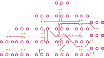
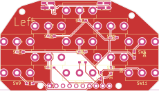
    Order your circuit boards

    Your setup decides which LYNX boards you need. You order them yourself, from the board house you choose, on your own account: LYNXware sells nothing and sees nothing of your order.

    No LYNX board can be ordered yet. None has a manufacturing release approved for anyone to order, so the order buttons stay closed. This section already shows what your build will need; ordering opens here, board by board, as each one is approved.

    1. The boards your build needs
    • Top of the Left finger module, 21 keys

      Left finger module, 21 keys left-F21

      For the Left cat · you need 1

      Revision
      none released yet
      Release
      Experimental
      Design
      in review

      The design exists, but no manufacturing files have been made from it for an order.

      No manufacturing files are published for this board yet.

    • Top of the Left thumb module, 11 keys

      Left thumb module, 11 keys left-T11

      For the Left cat · you need 1

      Revision
      none released yet
      Release
      Experimental
      Design
      qualified

      The design exists, but no manufacturing files have been made from it for an order.

      No manufacturing files are published for this board yet.

    • Top of the Right finger module, 20 keys + scroll wheel

      Right finger module, 20 keys + scroll wheel right-F20W

      For the Right cat · you need 1

      Revision
      none released yet
      Release
      Experimental
      Design
      in review

      The design exists, but no manufacturing files have been made from it for an order.

      No manufacturing files are published for this board yet.

    • Top of the Right thumb module, 11 keys

      Right thumb module, 11 keys right-T11

      For the Right cat · you need 1

      Revision
      none released yet
      Release
      Experimental
      Design
      qualified

      The design exists, but no manufacturing files have been made from it for an order.

      No manufacturing files are published for this board yet.

    Bought ready-made, not from a board house: 2 × BPI-Leaf-S3 (ESP32-S3), 1 × LILYGO T-Dongle-S3. See the whole parts list.

    2. Assembled or bare?
    3. Where to order

    Prices, minimum quantities, part stock, taxes and shipping differ by board, country and day: compare them on each manufacturer’s own page. Neither is always cheaper or faster.

    4. Your order
    Manufacturer
    not chosen yet
    Assembly
    Bare boards
    Board types
    4
    Separate orders
    4 (one per board type)
    BoardRevisionNeededTo orderStatus
    Left finger module, 21 keys—1—No manufacturing files are published for this board yet.
    Left thumb module, 11 keys—1—No manufacturing files are published for this board yet.
    Right finger module, 20 keys + scroll wheel—1—No manufacturing files are published for this board yet.
    Right thumb module, 11 keys—1—No manufacturing files are published for this board yet.

    After the order you still:

    1. Buy the components on each board’s parts list and solder all of them yourself.
    2. Wire each module to its main board (the Build steps show how).
    3. No board house loads LYNX firmware: you flash it yourself in Flash firmware.

    Choose a manufacturer to see how to order.

    Technical details: files, settings and checksums
    Left finger module, 21 keys (left-F21)

    No manufacturing release. The design’s parts list and interactive BOM are on its board page, for reference only: they are not an order package.

    Left thumb module, 11 keys (left-T11)

    No manufacturing release. The design’s parts list and interactive BOM are on its board page, for reference only: they are not an order package.

    Right finger module, 20 keys + scroll wheel (right-F20W)

    No manufacturing release. The design’s parts list and interactive BOM are on its board page, for reference only: they are not an order package.

    Right thumb module, 11 keys (right-T11)

    No manufacturing release. The design’s parts list and interactive BOM are on its board page, for reference only: they are not an order package.

  2. Step 2: Solder the key switches and headers

    Left cat Right cat draft

    First: Order the module boards

    The module header goes on the bottom side: once soldered on the top, it does not come off without lifting its pads.

    Fit the K9-1267T switches from the top and solder them from below: the boards use pins 2 and 3, pin 1 stays open. Solder the module header on the bottom side.

    How you know it worked: Every switch sits flat on the board; with the multimeter, each switch closes between its row and column pads when pressed.

    Tools
    soldering iron, multimeter
  3. Step 3: Hand-solder the scroll-wheel encoder

    Right cat draft

    First: Order the module boards

    The EVQWGD001 encoder has no board-house assembly; solder it by hand. Its pad 6 stays unconnected.

    How you know it worked: The wheel turns freely and clicks; A, B and the push switch close to GND on the header.

    Tools
    soldering iron
  4. Step 4: Wire each module header to the cat main board

    Left cat Right cat draft

    First: Order the module boards

    A wire on the wrong pad can short a supply to ground: check each connection and its neighbours before you power the board.

    Connect every header pin to its GPIO pad on the main board, as the pinout lists it. The cable itself is not specified yet (wiring-harness.toml).

    How you know it worked: Each header pin reaches its GPIO pad and no neighbour (continuity test).

    Parts now
    Why this matters

    These wires carry every key, LED and sensor signal of the module to the cat's main board; the firmware reads each signal on one fixed GPIO, so a wire on another pad loses that signal.

Code

  1. Step 5: Get LYNX onto your computer

    Every device draft

    The firmware is built and flashed on your own computer, from a copy of the LYNX repository. You need Linux, git, Podman and Python 3.11 or newer, and your user in the dialout group to reach the boards over USB (sudo usermod -aG dialout "$USER", then log out and in again). Clone the repository, open a terminal in it and let ./lx doctor check the rest. Every build runs in a pinned container, so you install no compiler or toolchain.

    git clone <LYNX repository URL> lynx-v4
    cd lynx-v4
    ./lx doctor

    How you know it worked: `./lx doctor` reports nothing missing.

    Parts now
    • USB-C cable only for each cat unknown: data-capable; length
    Tools
    Linux computer
    Why this matters

    Your computer builds each board's firmware for exactly the modules you fitted, and keeps your devices' pairing keys: nothing of it leaves your computer.

    Something doesn't match

    ./lx doctor names something missing: install what it names, then run it again.

    Permission denied on /dev/ttyACM… later: your user is not in dialout yet. Add it as above, then log out and in again.

  2. Step 6: Open the setup page

    Every device draft

    First: Get LYNX onto your computer

    Start the setup page from the terminal in the repository, then open http://127.0.0.1:8770/ in any browser. The page only shows what you choose and how far each job is; the terminal's service builds and flashes. Its first start downloads the container image and builds the setup tool, which takes a while once. Keep the terminal open while you use the page; Ctrl-C ends it.

    ./lx setup ui

    How you know it worked: The browser shows the LYNX setup page, starting at step 1, Your setup.

    Why this matters

    One page takes you from your choice of modules to flashed and paired devices, in the order the boards need.

    Something doesn't match

    The terminal names a missing tool instead: install it, then start ./lx setup ui again.

    The page says the setup service does not answer: the terminal's service has stopped. Start ./lx setup ui again and reload the page.

  3. Step 7: Choose your setup on the page

    Every device draft

    First: Open the setup page

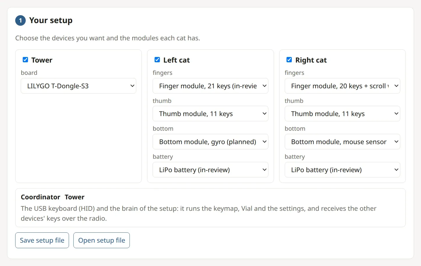
    In step 1, tick the devices you built (a tower, one or two cats) and pick each cat's modules as you fitted them; without a tower, choose which cat is the Coordinator, the one on the computer's cable. In step 2, pick each layer's LED colour and, for a hand with a mouse sensor or gyro, its speed and direction. Save setup file keeps your choices for later.

    How you know it worked: Step 1 shows no error under your setup, and the Coordinator line names the device you expect.

    Why this matters

    The firmware is built for the modules you choose here: a wrong choice builds a cat that does not read a module it has.

    The setup page at step 1, Your setup: a tower and two cats, each cat's modules chosen.
  4. Step 8: Plug in each board

    Every device draft

    First: Choose your setup on the page

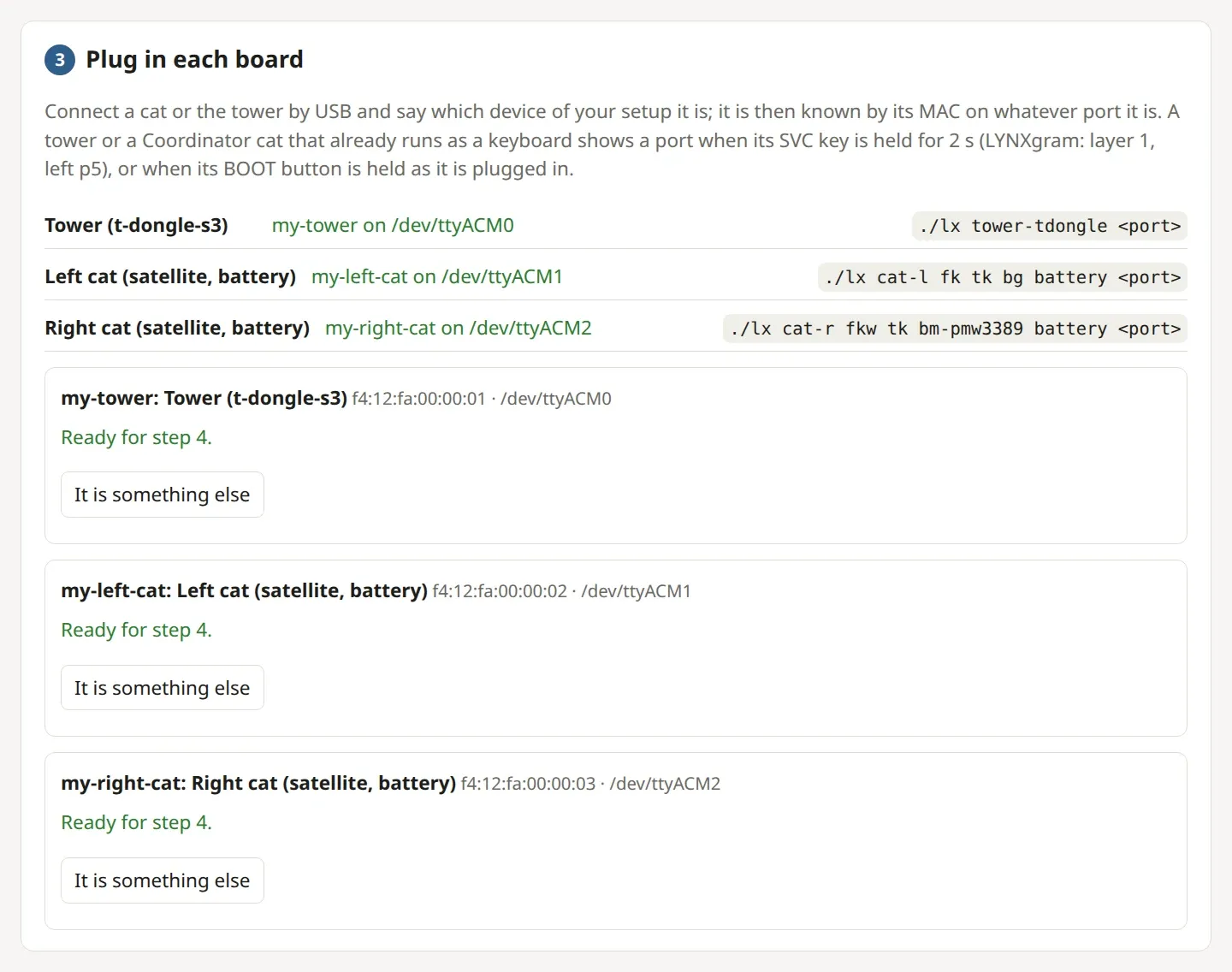
    Plug each board in by USB. Its card in step 3 asks which device of your setup it is: click the matching one. The page then knows the board by its MAC address on whatever port it is. A tower or a Coordinator cat that already runs LYNX is a keyboard and shows no port: hold its SVC key for 2 s (LYNXgram: layer 1, left p5) or plug it in with its BOOT button held.

    How you know it worked: Every device in step 3's list names its board and a port.

    Something doesn't match

    A board shows up as no card at all: try another cable, since some carry power only.

    A board shows up without a port: unplug it and plug it in again with its BOOT button held.

    The setup page at step 3, Plug in each board: all three boards assigned, each on its own port.
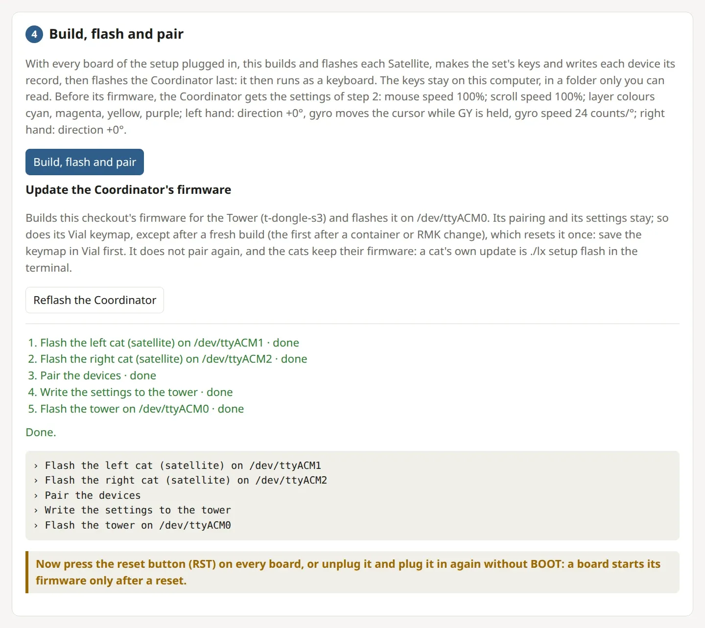
  5. Step 9: Build, flash and pair

    Every device draft

    First: Plug in each board

    Pairing makes new keys for every device of the setup, so keep every board plugged in until the job is done. A new set also tells the Coordinator which hands it serves: when that changes, its next boot replaces the stored keymap with the new default, your Vial edits included. Save your keymap in Vial first. Flash only from the page or ./lx: erasing the whole flash deletes a board's pairing record.

    With every board plugged in, click step 4's button. It builds and flashes each Satellite, makes your set's keys and writes each device its record, writes step 2's settings to the Coordinator and flashes the Coordinator last. A single cat has no one to pair with: its button only builds and flashes. When the job says Done, press each board's reset button (RST), or unplug it and plug it in again without BOOT.

    How you know it worked: After the reset, the Coordinator shows up on the computer as a keyboard (lynxTOWER, or lynxCAT and its side), and no cat's LED 1 stays solid red.

    Why this matters

    Each device gets the keys it shares with the others; without them a device stays silent by design and pairs with nothing. The keys stay on your computer, in a folder only you can read.

    Something doesn't match

    A cat's LED 1 stays solid red, or its log says UNPROVISIONED: it has no valid record. Run step 4 again with every board plugged in.

    The job fails at one board: its output names the board and why. Fix that, then run step 4 again: it starts over and makes a new set.

    A cat with a PMW3389 does not enter download mode from BOOT: the sensor's reset pull-up may hold a boot strap (unverified; see the pinout's strapping pins).

    The setup page at step 4, Build, flash and pair, with the job done: every board flashed and paired.
  6. Step 10: Set up your keys in Vial

    Every device draft

    First: Build, flash and pair

    Open vial.rocks in Chrome, Edge or another Chromium browser, or the Vial app, and choose your keyboard. On Linux it needs Vial's udev rule, once. Click a key, then the binding it should have; each change is saved on the keyboard at once. The LYNX keys are under Keymap › User, among them SVC for service mode, which changing the settings later uses (LYNXgram has it on layer 1 at left p5).

    How you know it worked: Vial finds the keyboard, and its key tester lights the keys you press.

    Why this matters

    The Coordinator keeps the keymap: the cats only report which key moved.

    Something doesn't match

    Vial finds no keyboard on Linux: add Vial's udev rule, then unplug the Coordinator and plug it in again.

  7. Step 11: Bench-test before closing anything

    Every device draft

    First: Solder the key switches and headers, Hand-solder the scroll-wheel encoder, Wire each module header to the cat main board, Build, flash and pair

    With everything still open: press every key, turn the wheel, move the sensor.

    How you know it worked: Vial's key tester lights every key, the pointer follows the sensor, and the thumb LEDs show the layer.

    Why this matters

    Every fault is easy to reach while the boards are open; once the lid is screwed down, finding a cold joint means taking the hand apart.

    Something doesn't match

    One key does not light: check that switch's solder joints and its diode's direction.

    A whole row or column stays dark: check that header wire end to end, and that it reaches its own GPIO pad and no neighbour (pinout).

Mechanics

  1. Step 13: Fit the LED plugs

    Left cat Right cat draft

    First: Print the enclosure parts

    Press a translucent LED plug into each of the thumb cover's two LED windows, its tab into the window's slot.

    How you know it worked: Each plug sits flush with the cover's surface.

Assembly

  1. Step 14: Mount each module board on its cover

    Left cat Right cat draft

    First: Bench-test before closing anything, Fit the LED plugs

    Seat each board on its cover's bosses, switches through the key cutouts, and screw it down with its four screws.

    How you know it worked: Every switch clicks through its cutout without rubbing.

    Parts now
    • M1.6 x 5 mm pan head screws, self-tapping for plastic unknown: a supplier and link; test-print a cover's boss and a casing boss for the pilot's grip
    Tools
    screwdriver
  2. Step 15: Put the modules into the casing

    Left cat Right cat draft

    First: Mount each module board on its cover

    Slide the finger and thumb modules into their slots in the casing, headers towards the inside.

    How you know it worked: Both modules sit in their slots without play.

  3. Step 16: Route the cables and seat the main board

    Left cat Right cat draft

    First: Put the modules into the casing

    Route the module cables and place the main board in the lid's board holder. A cat with a battery also takes the battery in its holder and the power switch in its holder, its slider through the lid's opening.

    How you know it worked: No cable is pinched where the lid will close.

    Parts now
  4. Step 17: Close the lid

    Left cat Right cat draft

    First: Route the cables and seat the main board

    A cable pinched between lid and casing can break or short: route every cable clear of the rim first.

    Lower the lid onto the casing and fasten its eight screws, their heads in the small pockets under the lid. Then stick a foot into each of the eight pockets, over its screw: a rubber pad, or on a hand with a mouse sensor a PTFE skate.

    How you know it worked: The lid closes flat all around.

    Parts now
    • M1.6 x 5 mm pan head screws, self-tapping for plastic unknown: a supplier and link; test-print a cover's boss and a casing boss for the pilot's grip
    • Self-adhesive rubber bumper pads, 8 x 3 mm only for No bottom module or Bottom module, gyro
    Tools
    screwdriver
  5. Step 18: Put on the keycaps

    Left cat Right cat draft

    First: Mount each module board on its cover

    Press a keycap onto every switch through its cutout.

    How you know it worked: Every key returns by itself and none rubs its neighbour.

Steps your build does not need (8)
  • Connect the mouse sensor

    draft

    Take its supply from the 3.3 V rail, not from USB's 5 V: the breakout runs from 3.3 V in this build and is not tried on 5 V.

    Wire the PMW3389 breakout to the main board's 3.3 V rail and its SPI pins, as the pinout lists them under the bottom slot's sensor breakouts.

    How you know it worked: The breakout's supply measures 3.3 V.

  • Connect the gyro

    draft

    Wire the GY-521's VCC to the main board's 3.3 V rail, and its SDA, SCL and INT to their pins, as the pinout lists them under the bottom slot's sensor breakouts. Leave its other pins open.

    How you know it worked: The breakout's VCC measures 3.3 V, and its power LED is lit.

    Why this matters

    The firmware reads the gyro on SDA and SCL; INT is wired for a later wake-on-motion and not read yet.

  • Connect the ADNS-5050 mouse module

    draft

    Its supply is the 5 V pin, not the 3.3 V rail: on 3.3 V the sensor does not start.

    Wire the module's 6-pin header to the main board's 5 V pin and its SPI pins, as the pinout lists them under the bottom slot's sensor breakouts. Clip the LED into the lens clip and the lens under the sensor.

    How you know it worked: With USB plugged in, the module's supply pin measures about 5 V.

    Why this matters

    The ADNS-5050 takes 5 V, which only the USB port gives the main board: this hand works as a mouse while it is plugged in, and has no battery.

  • Connect the battery

    draft

    Plug makers wire these 2-pin plugs either way round: measure the battery's plug before you plug it in. A LiPo connected the wrong way round damages the main board, and a shorted LiPo can overheat and burn. Cut and solder one lead at a time, so the two cut ends never touch.

    Cut the battery's + lead and solder its two ends to the power switch: the battery's end to the middle pin, the plug's end to an outer pin. Then plug the LiPo into the main board's battery socket, the 2-pin MX 1.25 mm socket beside the USB-C end. Its + contact is pin 1, the one marked + on the board.

    How you know it worked: With USB unplugged, the main board runs with the switch on and is dark with it off.

    Tools
    multimeter, soldering iron
    Why this matters

    The power switch sits in the battery's + lead, so the switch, not the USB cable, decides whether the cat runs on its own.

  • Give the PMW3389 its SROM (optional)

    draft

    First: Get LYNX onto your computer

    PixArt's sensor firmware is not part of LYNX. With your own copy, put it where the SROM notes say before the next step: the flash then writes it into its own partition after checking its SHA-256. Without it the sensor runs on its own ROM.

    How you know it worked: The cat's boot log says the SROM 0x47 was found, or that the sensor runs on its own ROM.

    Why this matters

    PixArt's firmware for the sensor, which LYNX may not redistribute: with it the PMW3389 tracks as PixArt intends.

  • Fit the bottom module

    draft

    First: Print the enclosure parts

    Screw the sensor breakout into the pocket of the mouse lid, beside the main board, lens facing down through the lid's window.

    How you know it worked: With the lid on its skates, the lens flange sits 2.2 to 2.6 mm above the desk (PMW3389 datasheet: 2.4 ± 0.2 mm).

    Tools
    screwdriver
  • Fit the gyro

    draft

    First: Print the enclosure parts

    Lay the GY-521 into the pocket of the gyro lid, beside the main board, its header's pin tails in the channel under the row, and screw it down through its two holes, a washer under each screw head.

    How you know it worked: The board lies flat and flush with its pocket and does not move.

    Tools
    screwdriver
  • Fit the ADNS-5050 mouse module

    draft

    First: Print the enclosure parts

    Lay the lens into its seat over the lid's window, flange down. Then fit the module's board over it, its 6-pin header towards the main board: tilt it, slide that long edge under its lip first, and press the other edge down until its lip snaps over it. The board has no screw holes: the lips hold it, and the sensor's aperture centres itself on the lens.

    How you know it worked: The board sits flat on its ledge under both lips and does not drop out with the lid turned over; the lens does not move.

© 2025-2026 lynx-v4 contributors · CERN-OHL-S-2.0 AND GPL-3.0-or-later